
Diesel Exhaust Gas Temp/ Boost Gauge
Transfer Case and Transmission Temp Gauge Article
Updated February 4, 2014
EGT Overview and Parts
 EGT means exhaust gas temperature. TIT means turbine inlet temperature. The temperature of the exhaust gas is a direct indicator of how hard the engine is working and if there is a problem. As the engine load increases more fuel is injected into the cylinders causing the exhaust gas temperature to rise. Your pistons are made of aluminum that melts at 1,220 degrees so over fueling, boosting or a malfunction (bad injector) could cause serious damage. If you have installed a performance chip or a supercharger this gauge is a must.
The hardest I've ever seen my stock truck work was while going up Loveland pass (11,100 feet) in Colorado which is a very steep highway. My wagon could have maintained 55 mph but I limited the speed to about 48 mph while keeping my EGT temperature below 1000. At times I saw the temp spike to 1,300 which according to the literature is the max temp you should run at. Easing up on the throttle dropped the temperature immediately. At the time, the water temp was running around 220 so the truck wasn't overheating. Note that 1997 and newer turbodiesels have oil sprayed on the pistons for additional cooling.
 An EGT gauge is a thermocouple pyrometer. If you install the sensor after the turbo you read exhaust temps. If you install the sensor before the turbo you read the turbine inlet temperature. Placing the probe at the turbine inlet results in higher temperature readings that react faster with changing engine conditions. Basically, the closer you can get the sensor to the exhaust port in the head the better. The reason you will see probes downstream of the turbo is to prevent a broken probe from trashing the turbo. I've had the same probe in my truck for over 5 years now without a problem. This is the same probe they sell for use in aircraft so I have a lot of confidence in this setup.
There are two kinds of boost gauges, mechanical and electronic. The mechanical units are basic pressure gauges that use a hollow curved tube (bourdon tube) that flexes under pressure. The electronic units have a transducer that senses pressure. These gauges are inherently damped and don't exhibit 'overshoot'. The electronic gauges do cost more.
 The goal I have in all my installations is to make them as clean as possible. I don't like to cut holes or butcher up the wiring harness.
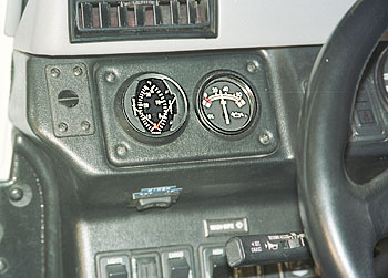
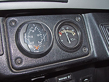
In my opinion the egt/ boost is more important than the voltmeter so I wanted it up high and visible. Installing it next to the important oil pressure gauge was my goal. I decided to install my new gauge where the voltmeter was. The voltmeter is not as important as the oil pressure or the egt. A drop in oil pressure or a sudden rise in egt could spell the end or your engine within seconds. If your voltage drops, the truck is not in danger of destroying itself and could very well run for hours more without a problem.
The voltmeter is easy to move because all it needs is a source of voltage from the truck. Since my 98 Hummer has a clock built into the Monsoon radio I decided I could live without the little round clock in the dash. Removing the clock gave me a nice existing hole for my new gauge with a 12v source for the voltmeter.
I found a great all in one dual gauge that reads both EGT and boost. Since EGT and boost are more important then volts I decided to install the new dual gauge where the voltmeter is on the upper left side of the dash and move the voltmeter where the clock used to be under the tach.
 The following is a list of parts for the project.
1/8" NPT tap and 'R' drill bit
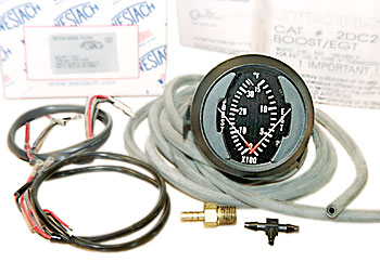
Westach
2" Dual EGT 100 - 1500F / Electronic Boost 0 - 35psi. Includes Gauge, 7' rubber hose, 2 hose fittings
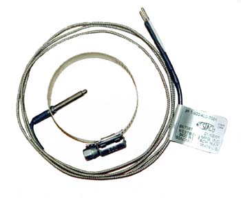
2DC2-30SS type k thermocouple wire EGT 1" Probe 1-5/8" to 2" round Clamp 4' steel braid lead 712-2DWK Illumination Light Kit.
The total price should be around 215.00 (back in 2001).
From Westberg Mfg.
Sonoma, CA (800) 400-7024
Westberg also makes mechanical boost gauges.
You can also get the Westberg products from Geno's Garage, in Georgia who is a supplier/re-seller. www.genosgarage.com and Wicks Aircraft in Highland Il. (near St. Louis). (800) 400-7024
If you want to go with separate gauges I liked the Isspro's. While their gauge is not a dual they make a very nice EGT Part No R607VW and R607T for TIT (127.00). The hose clamp thermocouple option adds 16.00 to the total. The 0 to 15 psi boost R8611R (37.00). You can get these and many other diesel products at Diesel Injection Services.
I also found a VDO pyrometer kit number 310153 (155.00) and a mechanical 0 to 25psi (30 in hg) 150-121 (35.00).
Installing the Gauges
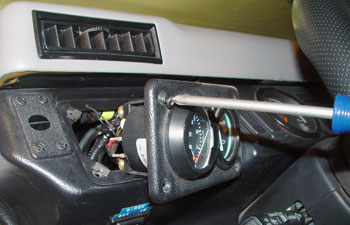 Remove the 4 trim screws from the voltmeter/ oil Pressure cluster and pull the black plastic panel away from the dash. Remove all the screws and wires from the voltmeter and pull it out of the panel.
 Insert the new gauge into the hole and install the plastic clamp. Cut off the ring connectors on the ground (black) and the 12v hot (gray) and strip the ends about 1/8”. Solder these ends to the supplied power harness that comes with the gauge. Use shrink tubing on the connections. Black to black and gray to red and push the black ground onto pin 5 and the gray hot on pin 4. Insert the light into the rear of the gauge and connect it to the violet dash light power wire making sure that you ground the other side of the lamp.
Remove the Clock and Replace it with the Voltmeter
Remove the 4 trim screws that hold the tachometer and clock cluster. Remove the clock (5/16” nuts)  and all the wires. The illuminator light comes out by twisting it ¼ turn. Insert the voltmeter into the hole and install the clamp. Connect the ground (black) to the center clamp hold down, and the gray, (hot) to the right side terminal. Take the light out of the voltmeter (twist and pull) and replace it with the one from the clock. The gray power is on all the time because it used to power the clock. This means that your voltmeter will read battery voltage when the truck is shut down. The voltmeter draws little or no current and could be useful to monitor voltage when you are using accessories with the engine off. If you don't like this setup just find an ignition switched hot and hook it up.
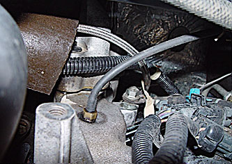
Install the Thermocouple Sensor
 Remove the dog house, rear engine cover and turbo heat shield.
Install the thermocouple in the stainless steel tube that goes from the exhaust manifold to the turbine inlet. This actually makes the instrument a Turbine Inlet Temperature (TIT) gauge.
Remove the clamp that holds the turbine inlet tube to the turbo and stuff a paper shop towel down the tube to catch any metal shavings that might drop in. Drill a 3/16” hole in the smooth section of the tube and pull the rag out.
 Slip the probe and clamp over the tube. Insert the probe in the tube, tighten the hose clamp and reconnect the inlet tube to the turbo and torque to spec.
Start the truck and make sure that there are no exhaust leaks. Replace the turbo heat shield, engine cover and doghouse.
 Another method is to use a good quality Cold-Weld compound to mount a pressure tap on the SS turbo tube. One of the members of my forum setup his system four years ago and it has remained stable and accurate.
ColdWeld will stick to stainless steel with no problem. It should be roughed up with coarse sandpaper before application. I tested it on the stainless steel intake tube and the adhesion was excellent.
The following product is sold for exhaust system repair for high temperature use on catalytic converters. It's rated to 2400f. It's called Thermosteel exhaust system repair kit part # 18022K and costs less than 10 bucks. (2009)
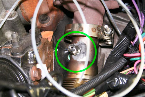
Pressure Tap for the Boost Gauge
 Put some grease on a sharp drill bit and slowly drill a hole in the drivers side intake manifold producing a nice ribbon of aluminum. The grease should catch any shavings from the drill before they fall into the manifold. It's a relatively thin casting so very little material is produced.
Next load the 1/8" (NPT) tap with grease and tap the hole. You can use a shop vacuum with a piece of small fuel line to suck any small chips out the hole Screw the supplied nipple into the manifold.
 The only thing left to do is to run the thermocouple wires and the boost tube to the rear of the gauge. I moved the CTIS pump and the window washer tank out of the way so I could drill a 1/2" hole in the firewall behind the pump. For my 98 I drilled the hole about 9- 1/2" from the edge of the truck. Before you drill remove the kick panel under the dash so you can see where your hole will come through the firewall. Believe me; it will ruin your day if you drill through a bundle of wires.
 I ran the rubber boost tube in the engine compartment along the top of the firewall with the window washer hoses. It was routed through the hole in the firewall and plugged into the rear of the gauge.
I fed the thermocouple wire from behind the engine through the hole in the firewall into the truck. Make sure that you join the thermocouple wires to the pigtail that goes to the gauge inside the truck. This is because the thermocouple actually measures the difference in temperature between the hot end (probe) and the pin terminals on the other end (cold junction). The thermocouple is calibrated for 75F at the cold junction. If you leave the cold junction in the engine compartment it will experience temperatures way over 75F most of the time causing inaccurate readings . Plug the two thermocouple wires onto the gauge connectors. Pin 1 goes to the white sender lead and pin 3 goes to the black.Neatly tuck all the wires back and close up the cluster panel.
When I started the truck I got no readings on the gauge. Once I started to drive things started to happen. A warm engine at idle might have a TIT of 200 to 300. Driving around the city gave me temps of 500 to 600. I got the temp to go as high as 900f when accelerating hard from a stop. You won't get any boost until you are moving. The max boost I have seen is 11 psi when accelerating hard from a light.
Installing the Pilot Light
 When I installed the gauge light I soldered a connector on one of the wires and slipped it around the ground screw on the oil pressure gauge. I attached the other to the violet dash light power using a spade connector. At first I used tube 'A' with a green boot. When I tried this arrangement out at night the light was so dim that you couldn't see the gauge unless the dash lights were turned up all the way. The solution is that you stack and glue the 'D' tube on top of the 'A' tube so the bulb sticks far enough into the gauge to be seen.
A Note on Cylindar Head Temperature (CHT) Gauges
CHT or Cylinder Head Temperature has it's roots once again in Aircraft engines.
When you're up in the air you can't have too many safeguards. This is not really critical for our Hummer engines but Hummer owners just love more guages and switches. Here are a few notes on doing an install.
CHT is more difficult, Since I had the head off anyway (thanks to a blown head gasket the truck came with) it was easier for me to put them on
Westach sells multi-sensor gages (up to 4) and there a ton of people that make various CHT alarms. Oh, and there are also clamp on probes and a number of other options depending on what your pleasure is there.
Fwiw I am using a MGL TG3 though as it was pretty much within $50 of the Westach and it ups the uber geek factor of the truck. Though it complicates the install a bit . Its not mounted where I want it (okay I admit, its wire-tied to the top of the dash when I am using it. Otherwise I have a plug to pull it off the truck and hide the evidence of my geeky ways.
