
Install A Speedometer with a Trip-Odometer and Trouble Shooting Speedo Problems
Updated May 14, 2023

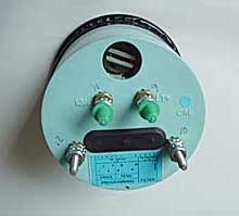
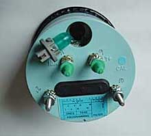
Above is a factory speedometer from a 1998 truck. There is one bulb in this unit for illumination which lines up at the 12:00 o'clock position on the face.
This solves another one of the "It should have come from the factory with this" items. Every car I ever had, had a trip odometer and I just got used to having one. I have a 95 gas wagon that gets about 9 to 10 miles per gallon on road and as low as 5 mpg off road. With a 23 gallon tank this doesn't get you far. I found myself writing down my mileage every time I filled up as an extra precaution against running out of gas. I also like to record distance between off road locations when following a map.
In '94 they changed from mechanical to electric speedometer so this won't work in 92's and 93's.
 The speedometer in the Hummer is a 3-3/8" diameter electronic programmable unit with a 0 to 100 mph range. A magnetic pickup in the rear of the transfer case (vehicle speed sensor) generates an electrical signal proportional to the rotational output speed. This signal is fed to the digital ratio adapter (DRA) which is a computer that accepts the pulsed signal. It converts it to a form that counts pulses per mile used by the speedometer and pulses per minute used by the Power train Control Module (PCM) which is the computer that controls the engine and transmission. This turns out to be a standard GM setup.
Extra information on the DRA
The DRA, the device that drives the speedometer actually has four outputs. One is used for the cruise control, one for the factory speedometer, and one is designated for the 'over speed alarm' that we don't have. I used the over speed alarm output to drive my rally computer, it is a single brown wire, with an unterminated connector, under the doghouse. Remember that this is a switch output, the DRA grounds this to form the pulses, so the speedometer you install will have to supply the voltage. In my rally computer setup, I used a 4.7K resistor from the 12V feed to provide this voltage. Its worked well for many years now.
VDO makes a speedometer that is programmable, electronically compatible and the right size that will work in a Hummer. The programmability is nice because if you change tire sizes or gear ratios you can adjust the speedometer to read accurately. The unit I picked back in 1995 was a 437 001 which is their cockpit style with mat black case, red pointer, white letters, a 0 to 85 mph range and a Trip Odometer. I've been told that the 0 to 85 mph models have been discontinued. The latest model as of 11/7/03 is the 437-052D which is the same as the one I have except the range is 0 to 120 mph. They still may have other models which are variations with chrome trim and 0 to 120 and 0 to 160 mph ranges. If the part number starts with 437, the diameter is 3-3/8" and it's a 12 volt model it will work in a Hummer. Part numbers get stale over time so do your homework before ordering. I believe they also have 24v models for you hmmwv owners. The speedometers cost around $125.00 to $140.00. When you order, you don't need a programmable sender or a GM adapter. I've also heard that an AutoMeter model 3986 will also work. I got my speedo from Summit Racing. They are also available at egauges.com.
The hardest part of the job is getting to the speedometer. As it turns out I did it the hard way. I took off the crash pad, removed the bottom kick panel, removed the bottom and left hand instrument panel mounting screws, removed the right and left hand gauges and managed to squeeze my hand behind the dash and very painfully unscrew and push the old unit out.
 After I completed the job I was telling a Mechanic at my Hummer dealer, what I had done. He had a laugh and told me that I went through all that pain and suffering for nothing. You just remove the plastic bottom kick panel, the one with the fuse box door. You then loosen two bolts on the steering column bracket; the pivot bolt and cross bolt. Then pull out the long bolt in the mounting bracket and the whole steering column assembly lowers down allowing easy access behind the dash. The only trick to the process is getting a hex wrench on the end of the bolt holding the steering column up. What you need to do is grind the wrench down so the 'L' section is shorter. Use a small 'ignition' wrench to remove the 2 nuts on the back of the speedometer.

You may need to replace the light bulbs in the VDO. After I installed the speedometer I found that at night the VDO was much dimmer than the other gauges due to differences in the supplied light bulbs. The Hummer's original speedometer uses one GE 154. My VDO came with two GE 54 bulbs which should be replaced with GE 47's. This is not a problem on newer units purchased after 1997.
Before you disconnect the old speedometer you should calibrate the new speedometer. There is a bank of ten small switches on the VDO that have to be set to the correct number of pulses per mile. I first used a mobile frequency counter hooked up to the yellow and black wires (signal in) to obtain a initial frequency reading at a known speed as a calibration start point. I then hooked up the new VDO in parallel with the original speedometer. I took a few test drives and fine tuned the settings until both were reading the same. I then took the truck for a highway test drive. I went 60 mph and verified that it took one minute between mile markers. VDO outlines a simple low tech way to calibrate their unit by running a known course to compute pulses per mile. I then wired in the VDO per the included diagram. Since I already performed the calibration you can probably use the same switch settings I used. I found that the 4132 to 4155 pulses per mile range worked fine.
The new speedometer works great and the 0 to 85 mph range is much easier to see. You can send the unit to VDO and they will set the unit to read your present mileage. You can also turn the unit up by setting the speedometer's dip switches to a low pulses per mile setting and use a signal generator to run the miles up. Note: you cannot turn the speedometer back.
Speedo - 437 152 (has LCD odometer and trip meter. VDO will set the odometer at the factory for your current mileage)
Notes and Remarks re. Installation
I started and completed my speedometer installation last night (well, actually, early this morning). It is VERY easy to get the new VDO gauge in. However, it is a giant pain in the ass to get the old speedo out.
Nonetheless, you first drop the steering column. Get creative when it comes to removing the four connectors from the old gauge. [BE VERY CAREFUL to keep track of which wire went where. The old speedo is well-marked, so once you remove it you can tell what each wire does if you know where it went (ign=ignition, lgt=lights, sgn= input signal from sensor, etc). The inputs are the same on the new VDO.] An ideal aide would be an 11/32" deep-socket ratchet! Anyhow, once you remove the four wires remove the other 11/32" nuts from the mounting arm. These nuts are on the same bolt as two of the wires.
Once you get those nuts off remove the mounting bracket and the speedo should come right out the front.
Unclip the old wiring harness, and make a new set of connectors for it. Connect the new harness to the gauge, slide it into the front of the dash, and tighten the threaded support. Don't forget to reconnect the harness.
If you're running up the miles on an electric odometer, you don't need to restrict yourself to the maximum gauge reading!!! If you have an 85mph speedo, you can still probably clock it at a 130mph rate. I found the VDO gauge I installed last night, though only an '85mph gauge,' would accept input up to (but not over -- it reverts to zero velocity) 130mph.
I spent the weekend doing some enhancements and I thought I should pass along what I found.
Black : Ground
Yellow : Signal from PCM
Gray : Lamp Power (+12)
Purple : Ignition 12v Power
How to run up the speedometer with a PC.
Items needed:
IBM type PC running DOS
3 wires w/clips on ends
voltmeter
GWBASIC or BASICA or QBASIC

Open your PC and find a spare power connector. Verify with your voltmeter before making connections the following pins on the connector. Yellow is +12 and connects to pin 4 of the speedo. Black is ground and connects to pin 3 of the speedo.
 Find pin 16 of the 25 pin D connector of the serial port and connect it to pin 8 of the speedo. Power up the PC while holding down the speedo button and release when the speedo display says PULSE. Follow the instructions and set the speedo to 500 pulses per mile.
Create a dos startup floppy disk by formatting a disk for startup. Put the speedometer program and a copy of basic on the disk. Boot the PC from the floppy disk. Running this in windows is probably not going to work.
Next, load GWBASIC and type in the following program:
10 T=590
20 INPUT "Steps per mile->",S
30 S=S/10
40 INPUT "Current odometer reading->",C
50 C=C*10
60 INPUT "Run till this odometer reading->",E
70 E=E*10
80 I=0
90 OUT &H3F8,232
100 FOR J=0 TO T
110 NEXT J
120 OUT &H3F8,236
130 FOR J=0 TO T
140 NEXT J
150 I=I+1
160 IF I < S GOTO 90
170 C=C+1
180 IF C < E GOTO 80
190 STOP
The variable T is used to control the pulse duration. Raise or lower T so that your speedo runs at the maximum display speed. My speedo has a top speed of 85 MPH, and on the PC I am using (25MHz 386), the value of T shown gives me full speed ahead. If your PC is faster, make the value of T (statement 10) larger. Start the program and look at the speed and adjust T accordingly. When you are ready to let 'er rip, go read your current odometer reading and use it when you start the program.
I'm not a Basic programmer, so no flames. The reason everything is done in tens is to avoid cumulative round off errors with floating point numbers (I did not want to have to figure out what the error might be, so I just made it not be a problem).
If you have QBASIC, use the following program:
T = 590
INPUT "Steps per mile->", S
S = S / 10
INPUT "Current odometer reading->", C
C = C * 10
INPUT "Run till this odometer reading->", E
E = E * 10
L0:
I = 0
L1:
OUT &H3F8, 232
FOR J = 0 TO T
NEXT J
OUT &H3F8, 236
FOR J = 0 TO T
NEXT J
I = I + 1
IF I < S GOTO L1
C = C + 1
PRINT C / 10
IF C < E GOTO L0
STOP
One additional note: On my PC, the first serial port is 3F8 which can be determined by going into the bios and looking at the port assignments for the serial ports. You can try loading DEBUG and entering D 40:8 and taking the first two bytes and making them a word and adding 2. Remember, it's in hex. If your machine's first port is not 3F8, then you will need to change the port shown in the OUT statements from &H3F8 to whatever your is.
I ran up a stock Hummer speedometer. I set T = 500 and steps per mile at 1000. The speedometer read 100 mpg and the odometer ran at around 300 mph. It was running on an old Pentium II celeron 500 using Win ME.
Speedometer Troubleshooting
The connector on the DRAC is not an automotive-grade
connector, and it often fails. There is not enough contact
pressure on the pins for a vibrating environment. If you
remove the connector and slightly bend the pins a small
amount in alternating directions, then carefully reconnect
it, it may cure your problem.
The DRAC is a small box about the size and shape of
a deck of playing cards. It is located in the center console,
and is usually accessible by removing the drink holder or
glove box.
I recently played submarine captain with a 95 H1 and now I am having some interesting issues with the speedometer. I already replaced the Speed Sensor, the digital ratio adapter and the speedometer along with alot of other things that didn't enjoy the experience. Here is the problem now, my speedometer reads while backing up but as soon as I go forward it reads periodically, sometimes reading fine and other times not at all, more off than on. The grounds are fine, I have 12 volts where I am supposed to, yet it still is doing these weird things. What am I missing, what have I overlooked???
Aside from wiring problems the first thing I would check is the pulses getting to the speedometer. I have a standard Fluke digital volt meter and it has a frequency selection on it. Hook this up to the ground and the pulse wire going to the speedometer. The speedo wants around 4000 pulses per mile. See if you are getting pulses to the speedometer all the time.
I checked and rechecked the pulses to the speedo and they would vary from 0 to 2700 pulses, I was always getting good readings while braking but no signal while not braking! Weird! So I started going thru the wiring diagrams for the brake circuit to see how it was linked to the speedo and why it was working when I pushed the brakes and not when on the gas!
Here's the answer; the Cruise Control module!!! It had swelled up so bad with corrision that it was making it's own circuit and controling things it never should!! I disconnected the module and Presto no more problem!!!
