
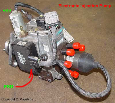
Stanadyne 6.5 Electronic Injection Pump
What's Inside, Timing & Optical Bump
Updated December 27, 2019
The prefix part # is a Stanadyne DS4831. After the DS4831 is a revision number that can be vehicle specific. There are DS4831-5068's, which are really designed for a 94 TD Chevy Diesel 3500 HD.
For our trucks, we should be using a DS4831-5288 or a DS4831-5521. Also look for a green metal tag on one corner of the IP - this generally means that the rebuilder has revamped it with the latest internal changes.
From what I can tell of the history, the DS4831-5067 is the first generation. Avoid these unless it's been upgraded with the ceramic rollers - the metal rollers inside them will shred unless you run an additive 24x7.
As for replacement - I'd consider having a Stanadyne shop do the work. It's a royal PITA to get to all the stuff you need to take one off and replace it. Local shops here in Phoenix charge about 1100-1200 dollars: pump removal, refurbish, and reinstall.
Shops sell a reconditioned DS4831 IP with new PMD for about 700 bucks. SS Diesel sells them on their web site for $655. On eBay, pumpguy246 sells refurbish DS4831's for $475, and running takeoffs for $50.
I have found used DS4831-5288's for sale as cheap as $24.
Article on the Mechanical Injection Pump
Stanadyne EFI injection pump, used from 1994 to 2004 in GM light duty pickups, delivery vans and in 1996 to 2004 model year Hummer turbo diesels. This injection pump can be used in naturally aspirated and turbo charged applications.
Problems can include a bad injector pump, the Fuel Solenoid Driver module (FSD) that sits on the injector pump on a turbo diesel only and the fuel shutoff solenoid (FSS). Not starting, stalling, hard starting, and hesitation are injection pump symptoms.
Note: The PMD is the same thing as an FSD. First, check that the engine is getting uncontaminated fuel and there is no water in the system. P0251 & P0370 will usually set if the vehicle has run out of fuel. Just so you are aware if water gets to the injectors, they will be destroyed. There are several ways that water is blocked, so it is unlikely this will happen. If you do suspect water in the fuel use a *diesel fuel compatible* fuel dryer.
Depending on the problem the truck may go into 'limp home' mode. When the timing signal is 'missing' the system will advance the timing to the max, hence the engine will get very noisy.
The trans doesn't up shift and you can drive about 30 MPH. Your engine will be running at higher RPM's due to this.
My 97 turbo diesel wagon would stop running for no reason at very unexpected times. After checking the fuel lines, lift pump and changing the fuel filter, I took it to a GMC dealer to have them run a computer scan on it. The scan from the tech 2 came back with the codes P0251 and P1216 both indicating a bad injector pump.
The codes being generated are generic OBDII codes that correspond to problems (on the 6.5L TD engine) that eventually will lead to the Injector Pump, the Pump Mounted Driver or the fuel shutoff solenoid being replaced. You may not find them in the AMG Service Manual.
p0251 (Injection Pump Fuel Metering Control) is the generic OBDII code that gets reported when the Stanadyne Injector pump can't read the optical sensor properly. p0370 (timing reference) is generally referring to the PMD or the electronics behind the optical sensor. p0251 will throw a "Check Engine" light. p0370 will not. Getting a p0251 will generally give you something else paired with it.
Definitely have the injector pump/PMD diagnosed. Best case - you dump a bunch of Stanadyne Fuel System additive in for a few weeks, clear the code out with the OBDII tool, and you'll never get it again. Worst case - you replace the Injector Pump and/or the PMD.
My Hummer has only 51,000 miles on which I do not think is a lot for this kind of diesel engine, so I called Stanadyne the manufacturer of the injector pump . After I read them the codes they explained that the optical sensor in the pump had failed. They gave me the model number of the pump used in all diesel hummers DS5521.
Stanadyne will supply a new pump with exchange for $900.00. They also recommended a local Stanadyne service center who will remove and replace the pump for a flat fee of $500.00. This is a big savings over the my hummer dealer who had told me that the pump and labor would cost between $2500.00 and $3000.00. Lookup Diesel in the Yellow pages to find a local dealer. Note that these prices may be outdated now.
Use a scan tool to clear the DTC (codes) but you must also cycle the ignition. You can also disconnect the battery which will supposedly clear the codes.
Fuel System Shutoff Solenoid
 This is what stops your engine when you shut it off. It is an electrically controlled valve that shuts off the flow of fuel to the injection pump. The valve can leak, the coil in the valve can go bad or you can have have failing electrical connections which will make it at best intermittent.
Thank Ross Schmitz for this great info. Symptoms are occasional hard starts, stall with sputtering during driving and would not restart right away. The last episode put my truck on the back of a flat bed for a ride home.
This differs from a FSD problem. Typically when you have a problem with the FSD the engine doesn't sputter and usually starts up fine. In the first stages of an FSD problem the engine will restart almost immediately or after the FSD cools down a bit. As the FSD gets worse it will get harder and harder to restart a hot engine.
The good news is that a FSS is easy to fix and fairly inexpensive (70.00 for a rebuilt in 2012). Replacement is very easy. Disconnect connector, and unscrew FSS (there is a 1/2" hex nut on top). Be careful when you remove it so you don't loose the coil spring that sits in the hole. Keep it clean and don't let dirt get into the pump. Install and torque to 200 in-lb per Stanadyne and reconnect wire.
Stanadyne says they bench check them with a 12 volt power supply to check actuation. I specifically asked if there is a resistance check and he said no (they have an electronic software assisted test stand for the entire pump). Also, he said they don't see these fail alot at all. Of the few they have had come back all failed either with a foriegn particle obstructing the valve on the inside of the unit or a bad coil.
Diesel Fuel Return line Kinked
This will kill your engine. The diesel engine requires a supply fuel line (fuel from the tank to the engine) and a return fuel line (fuel from the engine back to the tank). What happens is that the injection pump will supply more fuel than is necessary to the injector. The computer opens the injector for a duration based on the called for power, ie you stepping on the gas. After each cycle there is unused fuel that has to go somewhere. If it has nowhere to go you will have problems. It was demonstrated to me by taking your fingers and folding the short drain-back hose coming off the injection pump in half to pinch it shut; the engine very abruptly shut down, just like turning off the key would. Problem found, FINALLY. One of the rubber hoses at the back of the engine was folding into a "Z" shape when the truck flexes in that direction, cutting off the flow of fuel.
These lines can get eaten by the newer blends of biodiesel which will disintegrate them and fail. New biodiesel lines are viton lined. These hoses will say SAE30R9.
Smell Fuel on the Engine
Has the engine got a misfire or hesitation? If it doesn't then most likely it is a return line or the injection pump itself. You can use a shop drop light and a mirror to see where the leak is. the return line is the line that comes out of the top of the injection pump and will split off and connect all the fuel injector return lines back to the tank. I've also had a leak in the fuel line entering the fuel filter bowl.
Blows a Ton of White Smoke and Idles Very Rough
I replaced the glow plug controller.
My truck still blows a ton of white smoke and still idles very rough, to the point it's now nearly stalling until the engine warms up. It will run, skip/rattle, then run, skip/rattle, so on, so forth. The rough starts are occurring whether the engine is warm or cold, block heater used or not. It doesn't settle down until I've got the thing running at highway speed, and then the truck finally runs "normal", until I turn it off again.
In troubleshooting everything (as things have degraded), I've replaced or tested:
- Glow Plugs
- Glow Plug Controller
- Injectors (thanks to Southwest Diesel)
- Glow Plug Harness (taking each glow plug wire off and testing it with a
VOM when someone turns the ignition to where the Glow Plugs are energized,
voltage is ~11v)
- +12v wire from battery to Glow Plug Controller (I get 12.2-12.6v at this
terminal), both at the wire lead as well as on the terminal itself.
- New air filter (had to try it....)
- Lift pump blasts fuel out (with a big mess...), but is slightly noisy
(somewhat expected)
I'm seriously debating doing the following:
- Draining/purging fuel lines (including the water drain off, despite the
fact that no idiot light for the drain is showing)
- Moving the injector pump by rotating it very minimally both clockwise and
counterclockwise to change the timing (or what the service manual calls the
TDC offset, page 2-109 for the 1998 Hummer)
Well, I've finally tracked down the problem (hard starting and missing timing issue for my 97.5 4 Door Hard Top). Took me a while, but it finally came to me while tracking down another theoretical leak in my oil pan. Come to find out that the oil leak from my pan isn't the pan gasket. It's diesel coming from the injector pump. So the problem is a shot injector pump.
Bad Injector
I had a 6.2 with a bad nozzle that was squirting not spraying.
It did a perfect job of "torching" a small hole through the top of a piston.
A word of advice. Some injector and pump shops install all new nozzle tips on
their "REMAN" units and some will clean and test only. Spend the extra $ for
the new tips.
If your engine develops a bad knock it is probably due to a bad injector. What happens is that the injector opens (much) earlier than it should, effectively advancing the cylinder timing which causes the knock. Others have reported that this is a beginning symptom of bad crankshaft bearings.
I have a knock in Cylinder #1 In my 99 H1. I cracked (loosened) the fuel injector line (to reduce fuel pressure) and the knock goes away. Any ideas
Could be a partially blocked injector, when they are blocked it sounds like
the big end is gone.
To prove whether it is the injector swap it with the next one and see if the
problem follows the injector. If you have a scan tool, you can disable that injector completely and
see if that affects the noise (td's only).
Do a compression test on cylinder 1 and on #3. Make sure the #1 injector did not over-pressure
the cylinder causing a hydrolock condition which would bend the connecting rod. The compression will be around 80-100 psi lower
than cylinder #3 if this is the case. I have seen around 4 hummers with this problem in the last year(2004). Replace the connecting rod and bearing and the
knocking noise will go away.
Injection Timing White Smoke
Injection timing that is too far retarded will allow more white smoke production for an extended period following a cold start because ignition temperature is controlled in part by injection timing. The engine will most likely run a little rough as well as exhibit lower power than normal. Check the injection timing first for an excessive white smoke problem. This check should include a test of the HPCA function. An inoperative HPCA solenoid due to an electrical problem or bad solenoid will produce an unusually large amount of white smoke while cold.
The HPCA solenoid makes it easier to start a cold engine by reducing housing fuel pressure in the advance mechanism. The HPCA solenoid is located under the fuel return outlet, under the pump housing cover. It is activated by the coolant temperature switch, which is mounted on the rear of the passenger side cylinder head. When coolant temperature is low the temperature switch is closed, energizing the HPCA solenoid (rear pump terminal connected with a green wire), which lifts the check ball off its seat in the return outlet. This reduces housing pressure to near zero, so that the transfer pump pressure behind the power advance piston can easily advance the cam ring. The HPCA advances the timing by about 6 degrees to compensate for the slower burning injected diesel charge until the engine warms up to around 125F.
Air in injection system
Air in an injector line won't allow that particular cylinder to fire during a cold start and this cylinder will lag behind the others in warming up. When the air is eventually purged from the affected injector line, the cylinder will begin to fire and will produce white smoke for a short period of time.
A constant air leak in the injection system will affect combustion efficiency and can allow white smoke generation for a longer period of time.
Injection Pump Housing Pressure
If the fuel return function in the injection pump becomes restricted and the internal pump housing pressure rises above the normal 10-12 psi, the injection timing will be affected. Housing pressure partially controls injection timing. More pressure retards timing, and less pressure advances injection timing. The engine will probably produce more white smoke due to lower combustion temperatures with a retarded timing. An incorrect housing pressure also interferes with the injection pump's ability to correctly meter fuel. Installing a "T" fitting in the injection pump fuel return line will allow you to test the return line pressure. The pressure should be below 12 psi. A higher reading would indicate a restricted fuel return line.
Injection Pump and Injectors
An injection pump with stuck or defective advance mechanisms can cause the engine to smoke abnormally. A timing test performed with an electronic timing set would help discover this problem. If you have a relatively low time pump and injectors, have them tested at a Stanadyne authorized re-manufacturing facility before considering replacement unless they are under warranty.
Timing the Electronic Pump
I was playing with my Autoenginutiy scan tool v4.0.. got connected in enhanced GM mode with the same config as you. For me the 'time set' thing is what i'm interested in - for months now I have been in a constant back and forth with my local dealership after they installed my new injection pump - things have never felt right since. John Klatte told me that in 'time set' mode i should get a reading of 3.5 otherwise the timing is off... but until now I have not been able to put the PCM in that mode .Tonight as I set that switch I watched 'desired IP timing' fall to zero as expected; and then watched the 'actual IP timing figure' as it wavered between 2.6 and 2.9 !! Lots of smoke billowing out of the engine at this point so I turned that mode off, but I think i've got some concrete proof now that they did not set the timing on my IP properly.
Did you do the "TDC Offset Learn"?
You can accomplish this by running the engine at idle speed until the coolant reaches normal operating temperature, select TDC OFFSET LEARN with the scan tool, it will take approx. 20 seconds to complete the task.
Correct learned TDC offset value should be between minus 0.25 and minus 0.75. If the value is not within specified range, loosen injection pump and rotate it to the correct value as follows:
If value is between plus 1.0 and minus 0.25, rotate the pump toward driver side till it achieves specified value.
If value is between minus 0.75 and minus 2.0, rotate pump toward passenger to achieve specified value.
Note: 1 mm pump movement in either direction results in approximately 2 degrees change.
As far as I know, once you achieve TDC offset value within the specified range, the PCM will control the injection timing based on the feedback it receives from various sensors.
Once the TDC offset is within the specified range, the PCM should control the pump timing via the stepper motor based on the input from the various sensors.
Again only the NA Diesel injection timing is adjustable. The Turbo Diesel injection timing is controlled by the PCM and is not adjustable.
If everything is working properly, the actual injector timing should closely resemble the desired injection timing.
On my particular vehicle, The TDC Offset Value reads minus 1.06. At idle, the desired injection pump timing reads 8.7 and the actual injection pump timing reads 8.6. Based on this, I should rotate the pump slightly toward the passenger side. However, the vehicle seems to run fine as currently set.
When connecting. you select Hummer H1 and then you are presented with a number of choices for engine type:
> 6.5 liter L56
> 6.5 lit re L57
> 6.5 lit re L65
Use the L65. That is the engine in our trucks. Go to the time set function, with warm engine. When the desired timing goes to zero, watch the actual timing. It will vary somewhat and you should still be able to read what looks like an average reading. It may swing a little, about .5 degrees plus or minus. If it swings much higher like say, 2 or 3 degrees, then you may have a problem with the gear train.
Optical Bump
While finding more information about Stanadyne PMD/FSD's I came
across this fascinating little tidbit about the optical sensor and how it
can be tweaked to provide more power. I have no idea if this actually works.
This seems to work very similarly to the rotation of the entire IP, but with
far less work and only the following common tools:
T-27 Torx bit
Snap Ring Pliers
T-40 Torx bit
A scribe
Two screwdrivers
The task is this - remove the top cover of the IP. You'll see the optical
sensor there. Use the T-27 bit and the snap ring pliers to remove the cover
and free up the optical sensor upper half.
The lower half is held in with a T-40 screw and a plate. Supposedly,
shifting the optical sensor 1mm will achieve power gains. Scribe the area
under the lock plate (Stanadyne supposedly does this already, but some pumps
don't have a guide mark), unscrew the T-40 partially, take a screwdriver,
and shift the lower sensor assembly 1mm towards the passenger side. Use
another screwdriver to hold the lock plate in place. Tighten everything and
reassemble.
Supposedly, power increases and there is either a negligable or minor increase
in MPG. And you don't need any special tools to rotate or loosen the IP.
Pictures of the optical sensor removal/replacement can be found here:
Pictures and a brief discussion on the "Optical Bump"
More stuff on the "Optical Bump"
Great thread about DS4 IP's.
