
Hummer’s Meritor Wabco ABS Modulator
Updated January 20, 2015

The code 2-6 gives a shuttle valve switch failure as the cause and the fix is to replace the entire modulator assembly.
- Complete ABS modulator unit part number SRB101203, ~$1800. Fits Land Rover Discovery II years 1999-2004. Made by WABCO in Germany.
- Official shuttle valve repair kit for the 2-6 error, p/n: SWO500040, $875. The kit includes the shuttle valve switches and the solenoid pack.
- Shutttle valve "small repair" kit: p/n : SWO500030 ~$70. Not recommended by Land Rover anymore.
I just picked up a new SWO500040 for $100 off of ebay. I'll report on the results. (8/2009)
Note: Looks like Land Rover mixed Oh's and Zeros. There is a single "Oh" after the W, the rest are zeros.
Following the service manual it is not too difficult to remove the modulator:
- Unplug battery,
- Remove drivers side splash shield, 3 bolts.
- Remove horn bracket/disconnect horns, 2 bolts.
- Disconnect hard lines from modulator, 4 lines to brakes, 2 from master cylinder.
- Remove the modulator bracket from frame, 4 bolts.
- Turn and twist contraption to pull bracket/modulator out from the top.
- Pull the leading edge up the bracket up and out first, allow the rest to come out behind it.
- Remove modulator from bracket, 4 bolts.
Here are some updated instructions (3/2014) sent in from one of my readers
The ABS unit failed again within 90 days after scraping and re-soldering the internal connector. I went to the Landrover site in your post and used option B (yes after removing the ABS pump again) and it has worked fine for over 2 years. End analysis, do the easier fix first (option B), unless you really like disassembling the left side of the engine compartment.
Here are some updated instructions (12/2011) sent in from one of my readers
Latest info. Falconworks makes a rebuild kit for the shuttle valves and seals. Made for the Discovery II, but matches up with 2002 H1 ABS just fine. Once taken apart, the ohm readings were fine on the old shuttle valves, but the soldering on the connector seemed to be the problem within the ABS modulator. When I jiggled the wires on the new shuttle switches, I lost ohm readings which is the source of 2-6 fault code. Once I scraped off the plastic behind the prongs and re-soldered the pins (I left the old connector plugged in so the pins would not fall out when re-soldering btw), both the old and new switches gave constant and proper ohm readings.
There is a work around to the entire black plastic connector problem that is included in the instructions. Apparently the black plastic connector merely sends signals from the shuttle valve switches (2 white round switches inside the black plastic housing under the ABS modulator) to the large 13 pin connector in the rear of the ABS modulator. Since the source of many problems is this internal/infernal piece, the wires from the shuttle valves can be run through the black plastic covering and one wire is simply grounded to the chasis and the other is connected to the wire corresponding with the signal pin. In the land rover it is shown in pic 42-44 in the link. I was able to re-solder the internal connector so I will leave it as is, but I would need to verify the same color wire in the harness if I continue to have problems.
Getting the modulator out is a real bear. Not anywhere near as easy as you see in the Land Rover examples.
The shuttle valves were unnecessary to replace but I already bought the kit for about $135 (Dec 2011) so I changed them. The seals on the internal pistons were leaking (I think). There was a lot of brake fluid residue around the unit so I assume it came from the leaky seals. The two seals are on the pistons for the shuttle valves themselves (1 seal per piston). Per Falconworks, after about 60k miles the seals begin to leak and I have around 60k miles...and I have a very small leak. But the leak did not seem to cause the fault, it was the crappy soldering job that requires the same amount of work to repair as rebuilding the seals/switches.
Basically if you get a 2-6 ABS failure, it is probably just a bad soldering job that can be fixed very easily...once you move heaven and earth to get to it.
More info on http://www.landroverclubvi.com/abs-mod.html (I took the link out because the site was infected in Jan of 2015. Hopefully they fixed it.) Look at Pictures 33-37 shows the source of the problem.
Here are some more specific instructions sent in from one of my readers
- I highly recommend the use of flare nut crows feet. Spray the flare nuts with PB Blaster the day before removal.
- The left splash shield must be removed in addition to the "three bolts", the hood latch and the harness loop in front (which requires a long extension and a 7/16" deep socket).
- Remove the stainless hoses from the master to the ABS. One hose can be positioned to drain back into the master. The other can be propped up as not to drain out.
- The entire ABS modulator bracket must be removed. The hardest part of this is getting a 7/16" open wrench around the harness loop fastener. It's gotta be done from the inside of the engine compartment which requires quite the body contortion to hold the wrench in place.
- To facilitate the removal of the modulator + bracket I dismounted and pushed aside the power steering pump and the CTIS pump.
- Once you get the modulator out of the car, it takes less than 30 minutes to take apart the modulator and install the new parts.
- I also ran 2.5L of brake fluid through the system, with power bleeder (motive products) and the air bubbles from the modulator just trickled out slowly.
I also ran 2.5L of brake fluid through the system, with power bleeder (motive products) and the air bubbles from the modulator just trickled out slowly.
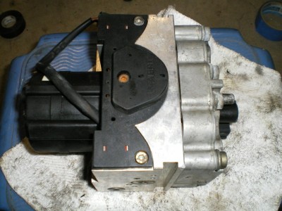
I found out that Land Rover Discovery Series II's use an identical modulator. You will see two different mounting holes on the pump motor side, one is for Hummer and one is for land rover.
You can install a modulator from a Land Rover Disco Series Two into our trucks. They cost used around $100 the on the internet. These are supposedly tested but further down I show you how to test it yourself. This led me to my next conclusion, if the modulator is the same then the shuttle valve is the same.
The shuttle valves can be purchased separately from Land Rover. It’s referred to as the shuttle valve repair kit and can be ordered for any Disco from 99'-04'. The shuttle valve repair kit is under $100 from Land Rover.
Once I removed the modulator I could jump the pins on the connector to test the shuttle valve. When connecting pins 6 and 9 (IIRC its connector C1, 13 pins) on the back of the modulator with an ohm meter I was getting nothing which means it was open. There should be some continuity between the two pins.
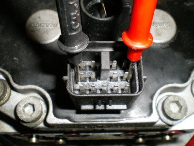 AM General’s shuttle valve test procedure is the same except you check the continuity directly at the ABS ECU connector (pins 25 and 27).
Okay so back on track. I got no continuity between pins 6 and 9. The shuttle valve is located on the bottom of the modulator. It’s a piece of black plastic that runs the length of the modulator and is held in with three Allen head screws.
 I found that when I tapped on the side of the shuttle valve with the ohm meter hooked up the connection was intermittent. Sometimes it was open and sometimes it was fine.
 I removed the shuttle valve assembly and realized when I moved the shuttle valve around I could get the connection to make and break.
I pulled the shuttle valve electrical connector off and removed the shuttle valve. I put the ohm meter across the two pin connector and started jiggling the wires. The connections were all good, there was a certain resistance at rest, another with one plunger pushed and another reading with both plungers pushed. This meant my shuttle valve was good. I found the pin in the connector was broken off the modulator circuit board.
 Here’s some insight into how the shuttle valve works. The plungers are activated by two different diameter plungers located within the modulator. The amount pressure you put on the brake pedal activates one of the two plungers telling the abs unit if you are not braking, lightly braking, or peddle to the metal braking.
I knew I had to fix the connector. I found another Land Rover owner who did this same repair. There are eight bolts holding the two halves of the modulator assembly together. Remove these eight bolts and make sure your shuttle valve is not connected.
 You might have to lightly pry the two halves apart and you will see the inner workings of the solenoids and valves that control your brakes and wheel spin for both abs and TT4. These silver rods move in and out in order to control which wheels receive the hydraulic pressure in the caliper. Don't worry there is nothing loose inside here that can fall out or move on its own.

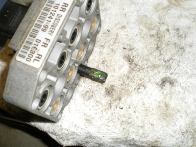 On the *lower* portion of the thin half of the case you will see a black plastic rod sticking out. It’s obvious. This is where the shuttle valve connects to the modulator circuit board.
 I found that this is what causes reoccurring shuttle valve problems (erratic lights on and off) and explains why some of my rebuilds would work and some wouldn't.
When they disconnected the old shuttle valve to put this one back in they would move this connection enough to get it back to having a solid connection within.
I figured that the broken pin due to a shoddy solder job at Meritor Wabco was the cause of my problem. Fixing it isn't that easy because the black plastic connector/circuit board is encased in hard plastic. I heated up a razor blade (in a handle) with my trusty torch and began surgery to remove that back half of the plastic rod. I used a soldering iron to heat up the "factory" solder and reinserted the pin. You have to hold the pins in the circuit board when heating the solder or they will fall out.
 I filed off some of the excess solder to make sure it would not contact the metal when I put the two halves back together. I put 3 coats of liquid electrical tape to seal up the connections.
I put all the pieces back together and put the trusty ohm meter back on. With the connections repaired I could hit the thing with a hammer and my readings wouldn't change. There was a good solid connection that shouldn't jar loose when hitting even a pot hole!
I fixed both the modulators I had which had tested bad for shuttle valves. I now have two modulators that are fully operational. I don't know the long term reliability of this solution but it seems as good or better than a new modulator.
I did find out that Land Rover released an updated version of their modulator around 2004. The two brass rings/washers on the top (when viewing installed in truck) are raised up slightly. It’s noticeable once you see both. I am not sure what the update was for.
Reinstall opposite of installation. Don't hook the batteries back up until you bleed the brakes. The batteries should be hooked up last, with the connections to the modulator next to last.
If this fix doesn't not work there is another option to bypass the circuit boards and run this as an external connection. Simply cut the connector off the shuttle valve, tap it into the wires located behind pins 6 and 9 respectively. You need to determine which wire goes to which pin, but this can be done by tracing with your ohm meter.
 I have a spare broken half of a modulator sitting here.
I saved the other half of my modulator, the one with the shuttle valve connector intact. I figure if this goes wrong again and I can't get the pins back in I will use that half to fix it!
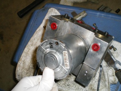
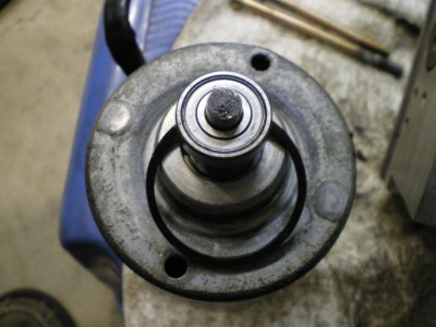
Here is what I did to the other half, the piece that holds the motor and looks like Sonic the Hedgehog on the other side!
Pull the cover off the motor and removed the two Allen screws holding the motor to the block (one broke in half actually, dissimilar metal welds?)
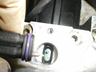
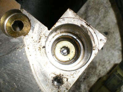
 Here is what it looks like under the motor. The two pins work as mini brake pedals; you push one in and it develops line out pressure on its respective half of the modulator.
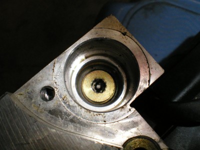
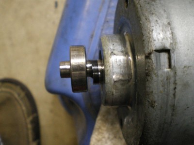
 Here is what activates those two pins. As the motor spins, this cam rides against the pins. You can kind of see how the cam is offset.
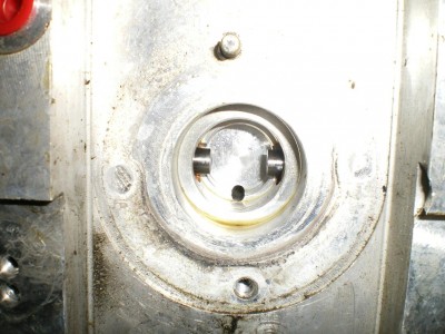
Here are two pics of the side of the modulator (and its O Ring!). As the motor spins the cam rolls side to side activating each plunger in sequence developing pressure to run the TT4 and ABS brake at each wheel. This is like two separate brake pedals, one controlling the left side calipers and one controlling the right side calipers.
So, I know you guys are asking yourself, Yeah that’s cool, but what are those plungers on the other side of the unit for?
The plungers are what control which wheel is receiving brake fluid and which ones are released from pressure. It will release pressure for the ABS side to work, and hold pressure or build pressure for the TT4 to work. TT4 essentially clamps down the caliper of the wheel that is spinning and lets the others free wheel so the torque is transferred to the wheel with traction.
I removed one of the "plungers". These go into a corresponding solenoid on the half of the modulator that is removed. Think of those as big magnets. When they are powered up they pull the plunger back and allow fluid to pass. I will assume some of the other pins pull back stop the flow of fluid.
 This shows where I believe the fluid comes in
 This is where it comes out?
 Here to?
 Side of pin, removed from block, seems like mesh in the oval opening of black rubber ring. Use of Vice Grips not recommended!
 Back Bottom of pin.
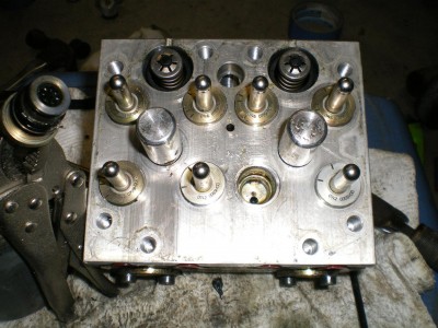
 These are some other plugs that I could unscrew. Some of them would not come out like.....the plugs where the pins of the shuttle valve are activated, the center big plug/screw on the side, and the small ones between the big holes under the shuttle valve.
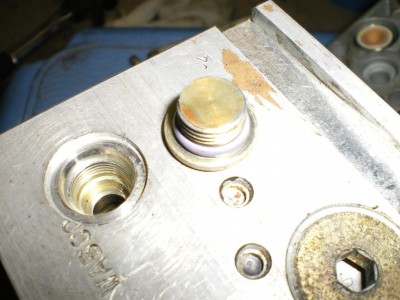
This is the big contraption right on the top of the modulator. There are two of these on the top and they are visible while the modulator is still installed. These are different on different revisions of the modulators BTW. One is recessed, one sits up higher....
 If you push on the black plastic in the center the cylinder moves down. Not sure what this does!
 This is the big spring thing on the same side as the plungers, I have no idea what these are for, but they have a large recess into the other side so I assume they move one way or the other. Vice Grips could not get this one to budge.
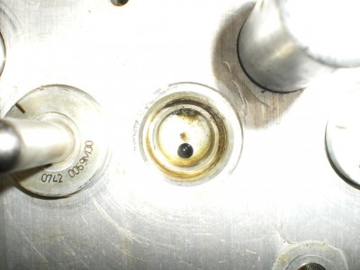
 This is the smaller of the two plugs on the side (I think it’s the side) of the housing. Have no idea what they do, but there are fluid transfer holes inside.
 My final conclusion from this is.......
There are a lot of places for air to get trapped!!!!
It’s no wonder that it’s highly recommended to pressure bleed the system from the master cylinder! There is no way my conventional bleeding can get all of these air pockets full.
I have had an air pocket behind one of the actuators and the pedal is nearly impossible to push, but the brakes do work! The fix, well I removed it to have it rebuilt, and lo and behold, I find out they don't touch that when rebuilding. So simply removing the unit and letting all the air back in was enough to reset the actuator. Reinstalled and it was good to go.
I have put some miles (and some bumps and bounces) on it now, enough for the code to come back if it was going to………………and no codes!
