
CTI Quick Disconnect Repair
Updated June 9, 2013
 First things first. What are these disconnects supposed to do and how do they work. Popping the disconnect by squeezing the metal latch disconnects the tire from the air system but it doesn't physically disconnect the two halves of the fitting. They do not separate like a normal disconnect on an air hose does. If you want to remove the disconnect you have to unscrew the actual fitting from the hub to physically remove the cti line. That's what you have to do when you change a tire.
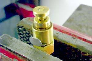
Just an FYI. The total height of the disconnect when it is locked down is 2-7/16" tall. This is from the bottom of the 1/4npt thread to the flat top.
For years I've been looking at these disconnects and never had the motivation to see how they came apart until one of them actually fell apart and revealed the secret.
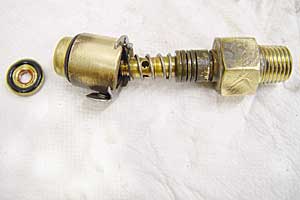
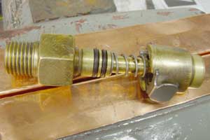
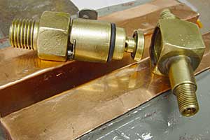
During a tire rotation one of my CTIS hub valve assemblies fell apart. (left photo) This let the air out of the tire. Visible in the photo is a threaded portion at the tip of the stem. When I looked inside the valve body (the part with the latch) I could see a threaded cap loose inside. I figured that since this was once assembled, it could be disassembled.
Note that there are 2 styles of this valve. The one in this article is the newer style. the older style has a hex surface about 1/2 as tall as the new one. The old style comes apart by clamping the top of the valve in a vise and tapping the hex hard enough around its periphery till it comes out. It then exposes a spindle with a few O rings you can replace.
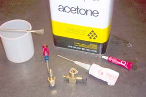
I gathered together the following: The valve, solvent; acetone or xylene and a small container and a brush, silicone grease, green or blue locktite plus an assortment of screwdrivers, wrenches and jewelers files. (right photo) A six inch shop vice with soft jaws and some scraps of 1/4" plywood make it all go pretty easily.


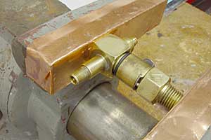
Then I put the Hex end into my shop vice. I have some soft copper jaw covers but you can also use scrap plywood over the jaws. I used a 5/8's open end wrench and levered under the top cap with a short pry bar to separate the top cap from the valve body. You can also turn the square part of the pry bar with a wrench to apply upward pressure. Work your way around both sides and be careful or you will damage the soft brass body and or bend the spool.
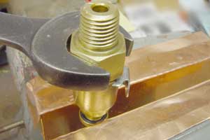
Next clamp the small brass disc in the vise. Be very careful not to apply too much pressure or you will bend and distort the disc. Put a 5/8" wrench on the hex and unscrew the disc as shown above.
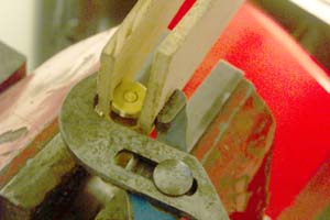
Another way to do the same thing is to clamp the hex end of the spool into the vise and use a pliers and some wood strips to remove the disc as shown below.

Once the disc is removed, the spool will pull out of the valve body. Don't loose the spring. At this point I cleaned all the parts with the acetone and a small brush. The top right photo shows what happens when you pry too hard. The soft brass of the top cap was deformed in the O ring seating area. I had to touch it up with a rotary burr.


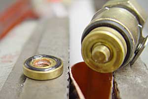
Check all the O rings, there are five, two on the stem, one on the square part of the valve and one under the "disc" and another one hidden inside the valve body (left photo). Replace as needed, they are standard rings. When you replace the inside ring push it into the body as shown and stuff it in the rest of the way with a small screwdriver. Make sure it seats correctly and doesn't bunch up.
While there is no need to disassemble the stainless latching device you might want to for repair and cleanup. Remove the tiny round pin by pushing it all the way into the body and sliding the latch past it and out. Careful, as there is a tiny spring under the pin and another spring behind the latch that might go flying. Set all these aside where you won't loose them.
When I took the valve apart, I had slightly deformed the lips that hold the latch in place and the hole that the keeper pin fits into. Using a small jeweler's file and a #33 drill bit (turned by hand) I was able to restore a good free fit to all the parts. I also bent the stainless latch which I straightened with a few hammer taps on a flat surface and a pliers.

Pry the O ring out of the disc and make sure the seating surface is clean. Glue in a new O ring. Make sure you don't get any glue on the top sealing surface of the ring. Install 2 new O rings on the spool and cover them with silicone grease. Install the spring over the spool.
If you took the latch apart assemble the latch, latch spring, keeper pin and pin spring onto the round part of the valve body,
Put the valve body on the spool and push it down till it latches. Clean the threaded tip of the stem with solvent and dry it off. Apply a bit of locktite on the threads and screw the cap in place hand tight. Put the assembly in the vise and tighten the disc onto the end of the spool using one of the methods used in removal. Wipe off any excess locktite and apply silicone grease to the O ring on the disc.
I then stretched a new large O ring that seals the top cap over the valve body and smeared on a bit of grease (left photo). I then cleaned the mating surfaces of the valve body and top cap. Put a light coat of locktite in the bore if you suspect that the brass is worn enough so it won't hold the valve together with the press fit alone. Using a shop vice with soft jaws I pressed the remaining two parts together. (right photo)
That is pretty much it, it took me about a half an hour to do the job and so far it is working just fine. Be aware that some of these are just too worn to be repaired. I did about 5 or 6 and at least 2 of them still leaked. A word of caution here: Acetone and xylene are flammable and care should be taken in their use. Read and follow the cautions on the can. Wear your safety glasses, work in a ventilated area, take your time and be meticulous about cleaning and greasing the correct parts and you should be successful.
